Difference between revisions of "Time reversal"
(→Theoretical results (homogenous medium only)) |
|||
| (30 intermediate revisions by 2 users not shown) | |||
| Line 1: | Line 1: | ||
| − | {{ | + | {{metamodelGetDP|time_reversal}} |
== Additional information == | == Additional information == | ||
| Line 7: | Line 7: | ||
=== The experiment and the code === | === The experiment and the code === | ||
| − | The | + | The model presented here was used in the PhD of B. Thierry <ref name=PhDThierry>B. Thierry, ''Analyse et Simulations Numériques du Retournement Temporel et de la Diffraction Multiple'', PhD. Thesis, Université de Nancy, France, 2011, http://tel.archives-ouvertes.fr/tel-00651312/</ref> (who also wrote the code) to study the super resolution phenomenon in a deterministic medium and in the time harmonic regime. |
==== Time reversal mirrors ==== | ==== Time reversal mirrors ==== | ||
| − | The principle of time reversal is to use the reversibility of the | + | The principle of time reversal is to use the reversibility of the wave equation in non dissipative media to back-propagate a signal on the source that first emitted it<ref>M. Fink and C. Prada. ''Acoustic time-reversal mirrors''. Inverse Problems, 17(1) :1761–1773, 2001. </ref>. Time Reversal Mirrors (TRM), designed by Matthias Fink and his team in the 90's, are composed of a large number of transducers which can play alternatively the role of emitters and receivers. Associated to a numerical treatment module, they are able to record a signal, time reverse it, and back propagate it into the medium. The applications are numerous, such as submarine communication or kidney stone destruction. |
| − | ==== Super resolution | + | ==== Super resolution phenomenon ==== |
| − | In a homogeneous medium, the wave back-propagated by the TRM | + | In a homogeneous medium, the wave back-propagated by the TRM focuses the source with a resolution generally given by |
$$ | $$ | ||
R = \frac{\lambda d}{a}, | R = \frac{\lambda d}{a}, | ||
| Line 23: | Line 23: | ||
* $d$ is the distance between the TRM and the source | * $d$ is the distance between the TRM and the source | ||
* $a$ is the aperture of the TRM (its size for a linear mirror) | * $a$ is the aperture of the TRM (its size for a linear mirror) | ||
| − | When the medium is heterogeneous, it is well-known that the back propagated wave will still focus on the point source with moreover a more accurate precision than in the homogeneous medium. In the litterature, this is generally imputed to the multi-pathing effect: the multiple scattering | + | When the medium is heterogeneous, it is well-known that the back propagated wave will still focus on the point source with moreover a more accurate precision than in the homogeneous medium. In the litterature, this is generally imputed to the multi-pathing effect: the multiple scattering produces multiple paths between the sources and the mirror, which then receives more information compared to the same experiment in a homogeneous medium. |
==== Time reversal experiment ==== | ==== Time reversal experiment ==== | ||
| − | Consider a point source $\mathbf{s}$ and a rectangular time reversal mirror $\mathcal{M}$ placed at finite distance of the source. The experiment can be split into three | + | Consider a point source $\mathbf{s}$ and a rectangular time reversal mirror $\mathcal{M}$ placed at finite distance of the source. The experiment can be split into three steps |
* First, the source emits a wave that propagates throughout the medium | * First, the source emits a wave that propagates throughout the medium | ||
| − | * Second, | + | * Second, the TRM receives and records the wave |
* Finally, it back-propagates it into the medium. The back-propagated field should then focus on the point source. | * Finally, it back-propagates it into the medium. The back-propagated field should then focus on the point source. | ||
The context of the experiment is the following: | The context of the experiment is the following: | ||
| − | * The time reversal mirror is non intrusive (does not reflect waves), continuous and thick. This last condition is to avoid | + | * The time reversal mirror is non intrusive (does not reflect waves), continuous and thick. This last condition is to avoid cracks in the mesh. |
* Waves are assumed to be time harmonic of pulsation $\omega$: $\mathscr{U}(\mathbf{x}, t) = u(\mathbf{x})e^{-ikct}$, where $k= \omega/c$ and $c$ is the speed of sound in the vacuum. | * Waves are assumed to be time harmonic of pulsation $\omega$: $\mathscr{U}(\mathbf{x}, t) = u(\mathbf{x})e^{-ikct}$, where $k= \omega/c$ and $c$ is the speed of sound in the vacuum. | ||
| − | ** The time-harmonic assumption implies that the time | + | ** The time-harmonic assumption implies that the time reversal operation is nothing but a phase conjugation. |
==== Context of the code ==== | ==== Context of the code ==== | ||
| − | The | + | The simulations presented here are achieved in the time-harmonic regime and in two dimensions. The equation to be solved is then the Helmholtz equation. The heterogeneous medium is modelled as multiple circular obstacles with an inner wavelength (a contrast). The wavenumber, even if not fully random, is still randomized by the position of the disks and the constrast function. The code allows to: |
| − | * Simulate the time reversal experiment in a homogeneous medium (no | + | * Simulate the time reversal experiment in a homogeneous medium (no obstacles) |
| − | * Study the super resolution | + | * Study the super resolution phenomenon by adding circular scaterrers between the source and the TRM |
| − | * For both | + | * For both media, monochromatic waves are available (one frequency) or point source waves with a bandwidth, which permits to simulate time-dependent problems (but is highly time consuming, in terms of CPU usage). |
In addition, the graphical interface allows to: | In addition, the graphical interface allows to: | ||
| Line 47: | Line 47: | ||
* Specify the aperture of the mirror | * Specify the aperture of the mirror | ||
* Add the obstacles, randomly placed in a customizable box. | * Add the obstacles, randomly placed in a customizable box. | ||
| − | * The contrast function can | + | * The contrast function can be ramdonized or be manually specified, either the same for each obstacle or not. |
=== Mathematical problem (monochromatic wave) === | === Mathematical problem (monochromatic wave) === | ||
| Line 72: | Line 72: | ||
\lim_{\|\mathbf{x}\|\to\infty} \frac{1}{\|\mathbf{x}\|^{1/2}}\left(\nabla u \cdot \frac{\mathbf{x}}{\|\mathbf{x}\|} - iku\right) = 0. | \lim_{\|\mathbf{x}\|\to\infty} \frac{1}{\|\mathbf{x}\|^{1/2}}\left(\nabla u \cdot \frac{\mathbf{x}}{\|\mathbf{x}\|} - iku\right) = 0. | ||
$$ | $$ | ||
| − | The unique solution of problem | + | The unique solution of problem \ref{eq:ue} is nothing but the Green function $G_k^n(\cdot, \mathbf{s})$ centered on $\mathbf{s}$. |
$$ | $$ | ||
\forall \mathbf{x}\neq\mathbf{s},\qquad u_E(\mathbf{x})= G_k^n(\mathbf{x},\mathbf{s}). | \forall \mathbf{x}\neq\mathbf{s},\qquad u_E(\mathbf{x})= G_k^n(\mathbf{x},\mathbf{s}). | ||
| Line 98: | Line 98: | ||
\forall \mathbf{y}\in \mathbb{R}^2\setminus\overline{\mathcal{M}}, \qquad u_{back}(\mathbf{y}) = \int_{\mathcal{M}} G_k^n(\mathbf{x},\mathbf{y}) \overline{G_k^n(\mathbf{x},\mathbf{s})}\; {\rm d}\mathbf{x}. | \forall \mathbf{y}\in \mathbb{R}^2\setminus\overline{\mathcal{M}}, \qquad u_{back}(\mathbf{y}) = \int_{\mathcal{M}} G_k^n(\mathbf{x},\mathbf{y}) \overline{G_k^n(\mathbf{x},\mathbf{s})}\; {\rm d}\mathbf{x}. | ||
$$ | $$ | ||
| − | For a homogeneous medium, as the Green function is known explicitely, so is the back propagated wave. This function can be plot directly with, ''e.g.'' a Python script, Matlab, Scilab, etc. With GMSH/GetDP, $u_{back}$ will however be computed by solving problem | + | For a homogeneous medium, as the Green function is known explicitely, so is the back propagated wave. This function can be plot directly with, ''e.g.'' a Python script, Matlab, Scilab, etc. With GMSH/GetDP, $u_{back}$ will however be computed by solving problem \ref{eq:uback}, but using the value of the Green function. For the heterogenous case and as the Green function is unknown, the emission and the back propagation steps are both computed numerically. |
==== Theoretical results (homogenous medium only) ==== | ==== Theoretical results (homogenous medium only) ==== | ||
| Line 115: | Line 115: | ||
The emitted wave $\mathscr{U}_E$ is then obtained by integrating over all the frequencies: | The emitted wave $\mathscr{U}_E$ is then obtained by integrating over all the frequencies: | ||
$$ | $$ | ||
| − | \mathscr{U}_E(\mathbf{x}, t) = \int_{k=k_0-\Delta_k}^{k_0+\Delta_k} u_E^k(\mathbf{x})e^{-i k | + | \mathscr{U}_E(\mathbf{x}, t) = \int_{k=k_0-\Delta_k}^{k_0+\Delta_k} u_E^k(\mathbf{x})e^{-i k ct}\;{\rm d}k |
| + | = \int_{k=k_0-\Delta_k}^{k_0+\Delta_k} G_k^n(\mathbf{x})e^{-i k ct}\;{\rm d}k, | ||
$$ | $$ | ||
| − | where | + | where $c$ is the velocity in the medium. |
| + | |||
| + | ==== Back propagated wave $\mathscr{U}_{back}$ by the TRM ==== | ||
| + | |||
| + | Recall that the expression of the back propagated field $u_{back}(\cdot\,,k)$ of frequency $k$, in the time harmonic regime, is given by, | ||
$$ | $$ | ||
| − | + | \forall k\in[k_0 - \Delta_{k},k_0 + \Delta_{k}],\forall\mathbf{y}\in\mathbb{R}^{3}\setminus\overline{\mathcal{M}},\qquad u_{back}(\mathbf{y},k) = \int_{\mathcal{M}}\overline{G_{k}^n(\mathbf{x},\mathbf{s})}G_{k}^n(\mathbf{x},\mathbf{y})\;{ | |
| + | \rm d}\mathbf{x}. | ||
$$ | $$ | ||
| − | + | The back propaged wave $\mathscr{U}_{back}$ is hence given by | |
$$ | $$ | ||
| − | + | \forall\mathbf{y}\in\mathbb{R}^{3}\setminus\overline{\mathcal{M}},\qquad \mathscr{U}_{back}(\mathbf{y},t) = \int_{k=k_0-\Delta_k}^{k_0+\Delta_k}\int_{\mathcal{M}}\overline{G_{k}^n(\mathbf{x},\mathbf{s})}G_{k}^n(\mathbf{x},\mathbf{y})\;{ | |
| + | \rm d}\mathbf{x} e^{-ikct}{\rm d}k. | ||
$$ | $$ | ||
| − | + | ||
| − | + | ==== $3$D and homogeneous medium: theoretical results ==== | |
| − | + | ||
| − | + | In the $3$D and homogeneous case, the expression of the emitted field reduces to | |
| − | |||
| − | |||
| − | |||
$$ | $$ | ||
| − | + | \forall t \in\mathbb{R}, \forall\mathbf{x}\in\mathbb{R}^{3}\setminus\{\mathbf{s}\}, \qquad \mathscr{U}_E(\mathbf{x},t) = \frac{\Delta_k{\rm sinc}\left[\Delta_k\left(\|\mathbf{x}-\mathbf{s}\|-ct\right)\right] e^{ik_0\left(\|\mathbf{x}-\mathbf{s}\| - ct\right)}}{2\pi\|\mathbf{x}-\mathbf{s}\|}, | |
$$ | $$ | ||
| − | + | where ${\rm sinc}(x) = \sin(x)/x$. Remark first that, due to the quantity $e^{ik_0\left(\|\mathbf{x}-\mathbf{s}\| - ct\right)}$, the wave $\mathscr{U}_E$ is propagating in a radial direction with respect to $\mathbf{s}$. The modulus of $\mathscr{U}_E(\mathbf{x},t)$ especially depends on the cardinal sine term, as: | |
| − | |||
| − | where ${\rm sinc}(x) = \sin(x)/x$ | ||
| − | |||
| − | |||
| − | |||
| − | |||
| − | Remark first that, due to the quantity $e^{ik_0\left(\|\mathbf{x}-\mathbf{s}\| - ct\right)}$, the wave $\mathscr{U}_E$ is propagating in a radial direction with respect to $\mathbf{s}$. The modulus of $\mathscr{U}_E(\mathbf{x},t)$ especially depends on the cardinal sine term, as: | ||
$$ | $$ | ||
\forall t \in\mathbb{R}, \forall\mathbf{x}\in\mathbb{R}^{3}\setminus\{\mathbf{s}\}, \qquad \left|\mathscr{U}_E(\mathbf{x},t)\right| = \left|\frac{\Delta_k{\rm sinc}\left[\Delta_k\left(\|\mathbf{x}-\mathbf{s}\|-ct\right)\right] }{2\pi\|\mathbf{x}-\mathbf{s}\|}\right|. | \forall t \in\mathbb{R}, \forall\mathbf{x}\in\mathbb{R}^{3}\setminus\{\mathbf{s}\}, \qquad \left|\mathscr{U}_E(\mathbf{x},t)\right| = \left|\frac{\Delta_k{\rm sinc}\left[\Delta_k\left(\|\mathbf{x}-\mathbf{s}\|-ct\right)\right] }{2\pi\|\mathbf{x}-\mathbf{s}\|}\right|. | ||
| Line 152: | Line 149: | ||
This quantity reaches its maximal value when $t = -D/c$. In other words, the perturbation created at time $t=0$ reaches the distance $D$ and thus the MRT, at time $t = D/c$. | This quantity reaches its maximal value when $t = -D/c$. In other words, the perturbation created at time $t=0$ reaches the distance $D$ and thus the MRT, at time $t = D/c$. | ||
| − | + | On the other hand, the back-propagated field reduces to: | |
| − | |||
| − | |||
| − | |||
| − | |||
| − | |||
| − | |||
| − | |||
| − | |||
| − | |||
| − | |||
| − | |||
| − | |||
| − | |||
| − | |||
| − | |||
| − | |||
| − | |||
| − | |||
| − | |||
| − | |||
| − | |||
| − | |||
| − | |||
| − | |||
\begin{equation}\label{eqRT:Ureyt} | \begin{equation}\label{eqRT:Ureyt} | ||
| − | + | \mathscr{U}_{back}(\mathbf{y},t) = 2{\rm d}k\int_{\mathcal{M}} | |
\frac{{\rm sinc}\left[{\rm d}k\left(\left[\|\mathbf{x}-\mathbf{y}\|-\|\mathbf{x}-\mathbf{s}\|\right] - ct\right)\right] | \frac{{\rm sinc}\left[{\rm d}k\left(\left[\|\mathbf{x}-\mathbf{y}\|-\|\mathbf{x}-\mathbf{s}\|\right] - ct\right)\right] | ||
e^{ik_0\left(\left[\|\mathbf{x}-\mathbf{y}\|-\|\mathbf{x}-\mathbf{s}\|\right]-ct\right)}}{\|\mathbf{x}-\mathbf{s}\|\|\mathbf{x}-\mathbf{y}\|} | e^{ik_0\left(\left[\|\mathbf{x}-\mathbf{y}\|-\|\mathbf{x}-\mathbf{s}\|\right]-ct\right)}}{\|\mathbf{x}-\mathbf{s}\|\|\mathbf{x}-\mathbf{y}\|} | ||
| Line 185: | Line 158: | ||
It should be pointed out that on the point $\mathbf{y}=\mathbf{s}$, the cardinal sine term vanishes and the above expression reduces to | It should be pointed out that on the point $\mathbf{y}=\mathbf{s}$, the cardinal sine term vanishes and the above expression reduces to | ||
$$ | $$ | ||
| − | + | \mathscr{U}_{back}(\mathbf{s},t) = 2{\rm d}k \int_{\mathcal{M}} | |
\frac{{\rm sinc}\left(-{\rm d}k ct\right)}{\|\mathbf{x}-\mathbf{s}\|^{2}} | \frac{{\rm sinc}\left(-{\rm d}k ct\right)}{\|\mathbf{x}-\mathbf{s}\|^{2}} | ||
\; {\rm d}\mathbf{x} = 2{\rm d}k{\rm sinc}\left({\rm d}k ct\right) \int_{\mathcal{M}} | \; {\rm d}\mathbf{x} = 2{\rm d}k{\rm sinc}\left({\rm d}k ct\right) \int_{\mathcal{M}} | ||
\frac{{\rm d}\mathbf{x}}{\|\mathbf{x}-\mathbf{s}\|^{2}}. | \frac{{\rm d}\mathbf{x}}{\|\mathbf{x}-\mathbf{s}\|^{2}}. | ||
$$ | $$ | ||
| − | Hence, when $\mathbf{y} = \mathbf{s}$, the modulus of $ | + | Hence, when $\mathbf{y} = \mathbf{s}$, the modulus of $\mathscr{U}_{back}(\mathbf{s},t)$ reaches its maximal value at time $t = 0$. On the other hand and on a point $\mathbf{y}\in\mathbb{R}^{3}\setminus\overline{\mathcal{M}}$, when $t=0$ the equality \ref{eqRT:Ureyt} becomes |
$$ | $$ | ||
| − | \forall\mathbf{y}\in\mathbb{R}^{3}\setminus\overline{\mathcal{M}},\qquad | + | \forall\mathbf{y}\in\mathbb{R}^{3}\setminus\overline{\mathcal{M}},\qquad \mathscr{U}_{back}(\mathbf{y},t = 0) = 2{\rm d}k\int_{\mathcal{M}} |
\frac{{\rm sinc}\left[{\rm d}k\left(\|\mathbf{x}-\mathbf{y}\|-\|\mathbf{x}-\mathbf{s}\|\right)\right] | \frac{{\rm sinc}\left[{\rm d}k\left(\|\mathbf{x}-\mathbf{y}\|-\|\mathbf{x}-\mathbf{s}\|\right)\right] | ||
e^{ik_0\left(\left[\|\mathbf{x}-\mathbf{y}\|-\|\mathbf{x}-\mathbf{s}\|\right]-ct\right)}}{\|\mathbf{x}-\mathbf{s}\|\|\mathbf{x}-\mathbf{y}\|} | e^{ik_0\left(\left[\|\mathbf{x}-\mathbf{y}\|-\|\mathbf{x}-\mathbf{s}\|\right]-ct\right)}}{\|\mathbf{x}-\mathbf{s}\|\|\mathbf{x}-\mathbf{y}\|} | ||
\;{\rm d}\mathbf{x}. | \;{\rm d}\mathbf{x}. | ||
$$ | $$ | ||
| − | On $\mathbf{y} = \mathbf{s}$, the quantity $ | + | On $\mathbf{y} = \mathbf{s}$, the quantity $\mathscr{U}_{back}(\mathbf{y},t = 0)$ does not depend on $k$ anymore and reads as |
$$ | $$ | ||
| − | + | \mathscr{U}_{back}(\mathbf{s},t = 0) = 2{\rm d}k\int_{\mathcal{M}} | |
\frac{{\rm d}\mathbf{x}}{\|\mathbf{x}-\mathbf{s}\|^{2}}. | \frac{{\rm d}\mathbf{x}}{\|\mathbf{x}-\mathbf{s}\|^{2}}. | ||
$$ | $$ | ||
| − | For every other point $\mathbf{y}$ (up to symetric points of $\mathbf{s}$ with respect to the TRM), the stationary phase theorem can be applied, as in | + | For every other point $\mathbf{y}$ (up to symetric points of $\mathbf{s}$ with respect to the TRM), the stationary phase theorem can be applied, as in the time harmonic regime. Hence, a decrease of $\left|\mathscr{U}_{back}(\mathbf{y},t = 0)\right|$ with respect to $k_0$ can be proven. This decrease is moreover stronger du to the presence of the cardinal sine term. As a consequence, at time $t = 0$, the wave $\mathscr{U}_{back}$ focuses on the point source $\mathbf{s}$. |
| − | Finally, remark that at $t=0$, the general expression | + | Finally, remark that at $t=0$, the general expression of $\mathscr{U}_{back}$, becomes |
$$ | $$ | ||
| − | \forall\mathbf{y}\in\mathbb{R}^{3}\setminus\overline{\mathcal{M}},\qquad | + | \forall\mathbf{y}\in\mathbb{R}^{3}\setminus\overline{\mathcal{M}},\qquad \mathscr{U}_{back}(\mathbf{y},t = 0) = \int_{k_0-{\rm d}k}^{k_0+{\rm d}k} \mathscr{U}_{back}(\mathbf{y},k) \;{\rm d} k. |
$$ | $$ | ||
| − | In other words, the wave $ | + | In other words, the wave $\mathscr{U}_{back}$ on $\mathbf{y}$ and at time $t=0$ is obtained by the sum of every time-harmonic fields $\mathscr{U}_{back}(\cdot\,,k)$, for $k\in[k_0-{\rm d}k,k_0+{\rm d}k]$. The quantity $\mathscr{U}_{back}(\mathbf{y},t = 0)$ can then be seen as an average over the frequencies $k$ of the different fields $u_{back}(\cdot\,,k)$. |
| − | === | + | === Numerical resolution === |
| − | To be solved using finite element method, problem | + | ==== Approximation with a PML ==== |
| + | To be solved using finite element method, problem \ref{eq:uback} is truncated using a Perfectly Matched Layer (PML), as in [[Acoustic_scattering|the scattering problem with a PML]]. | ||
| + | <!--First, let us build the domain $\Omega_{e}$ on which an approximation of the back propagated field will be computed. A rectangular shape for $\Omega_{e}$ is natural in that problem: | ||
$$ | $$ | ||
\begin{array}{rcl} | \begin{array}{rcl} | ||
| Line 247: | Line 222: | ||
\end{cases} | \end{cases} | ||
$$ | $$ | ||
| − | The functions $\sigma_{x_{1}}$ and $\sigma_{x_{2}}$ are called damping functions. When $\sigma_{x_{1}}$ and $\sigma_{x_{2}}$ are equal to zero, then equation | + | The functions $\sigma_{x_{1}}$ and $\sigma_{x_{2}}$ are called damping functions. When $\sigma_{x_{1}}$ and $\sigma_{x_{2}}$ are equal to zero, then equation \ref{eqRT:HelmholtzPML} reduce to (classical) Helmholtz equation, that is why in general, these functions vanish on $\Omega_{e}$. On the other hand, when the damping functions are positive, they act as a dissipative term in the equation. Remark that, by introducing the following matrix |
$$ | $$ | ||
D = \left[ | D = \left[ | ||
| Line 256: | Line 231: | ||
\right], | \right], | ||
$$ | $$ | ||
| − | then problem | + | then problem \ref{eqRT:HelmholtzPML} can be rewritten as |
\begin{equation}\label{eqRT:eqPML} | \begin{equation}\label{eqRT:eqPML} | ||
\left\{\begin{array}{r c l l} | \left\{\begin{array}{r c l l} | ||
| Line 280: | Line 255: | ||
Inside $\Omega_e$, the damping functions vanish whereas inside $\Omega_{PML}$, at least one of them do not vanish. Note that in the "corners" of $\Omega_{PML}$, both damping function are note equal to zero. | Inside $\Omega_e$, the damping functions vanish whereas inside $\Omega_{PML}$, at least one of them do not vanish. Note that in the "corners" of $\Omega_{PML}$, both damping function are note equal to zero. | ||
| − | Finally, let us just remark that the efficiency of the PML can be improved by using another type of damping functions, as quadratic functions or even functions with an infinite integral on $\Omega_{PML}$, as the one proposed by Bermudez et. al <ref>A. Bermúdez, L. Hervella-Nieto, A. Prieto and R. Rodríguez, ''An optimal perfectly matched layer with unbounded absorbing function for time-harmonic acoustic scattering problems'', J. Comput. Phys., 2007</ref>. | + | Finally, let us just remark that the efficiency of the PML can be improved by using another type of damping functions, as quadratic functions or even functions with an infinite integral on $\Omega_{PML}$, as the one proposed by Bermudez et. al <ref>A. Bermúdez, L. Hervella-Nieto, A. Prieto and R. Rodríguez, ''An optimal perfectly matched layer with unbounded absorbing function for time-harmonic acoustic scattering problems'', J. Comput. Phys., 2007</ref>.--> |
| − | === Weak formulation === | + | ==== Weak formulation ==== |
| − | To simplify, the approximation of the back propagated field in $\Omega_e$ is still denoted by $u_{back}$ instead of $u^{PML}_{back}$. Function $u_{back}$ will be sough in the Sobolev space $H^1(\Omega_T)$and the weak formulation of problem | + | To simplify, the approximation of the back propagated field in $\Omega_e$ is still denoted by $u_{back}$ instead of $u^{PML}_{back}$. Function $u_{back}$ will be sough in the Sobolev space $H^1(\Omega_T)$and the weak formulation of problem \ref{eq:uback} reads as |
$$ | $$ | ||
\left\{ | \left\{ | ||
| Line 296: | Line 271: | ||
\end{array}\right. | \end{array}\right. | ||
$$ | $$ | ||
| − | where $u_E$ is here equal to the Green function: $u_E = G(\cdot,\mathbf{s})$. | + | where $u_E$ is here equal to the Green function: $u_E = G(\cdot,\mathbf{s})$. |
| − | |||
| − | |||
| − | |||
| − | |||
| − | |||
| − | |||
| − | |||
| − | |||
| − | |||
| − | |||
| − | |||
| − | |||
| − | |||
| − | |||
| − | |||
| − | |||
| − | |||
| − | |||
| − | |||
=== Results === | === Results === | ||
| − | ==== | + | ==== Homogeneous medium ==== |
| − | The three following pictures | + | The three following pictures depict respectively the geometry, the real part of $u_{back}$ and the absolute value of $u_{back}$, with the following parameters ($\lambda_{geo} = 2\pi/k_{geo}$): |
* $k_{geo} = 10$ | * $k_{geo} = 10$ | ||
* Distance between source and mirror: $20\lambda_{geo}$ | * Distance between source and mirror: $20\lambda_{geo}$ | ||
| Line 329: | Line 285: | ||
* $k = k_{geo} = 10$ | * $k = k_{geo} = 10$ | ||
| − | [[File:TRFreeSpace_geo.png|250px|frameless|alt=Geometry|Geometry.]] | + | For a monochromatic wave of frequency $k_0=k_{geo}$, which corresponds to a harmonic source, the results are: |
| − | [[File:TRFreeSpace_Uback.jpg|250px|frameless|alt=Real part of the back propagated field|Real part of the back propagated field.]] | + | |
| − | [[File:TRFreeSpace_Uback_abs.jpg|250px|frameless|alt=Absolute value of the back propagated field|Absolute value of the back propagated field.]] | + | [[File:TRFreeSpace_geo.png|250px|frameless|alt=Geometry|Geometry and ONELAB interface for a homogeneous medium.]] |
| + | [[File:TRFreeSpace_Uback.jpg|250px|frameless|alt=Real part of the back propagated field in a heterohomogeneous medium (monochromatic wave|Real part of the back propagated field in a heterohomogeneous medium (monochromatic wave.]] | ||
| + | [[File:TRFreeSpace_Uback_abs.jpg|250px|frameless|alt=Absolute value of the back propagated field in a heterohomogeneous medium (monochromatic wave)|Absolute value of the back propagated field in a heterohomogeneous medium (monochromatic wave.]] | ||
| + | |||
| + | Now, using the same geometry, a polychromatic wave is used as emitted wave instead of a pulse. The frequency now lies between $[k_0-\Delta_k, k_0+\Delta_k]$ with $k_0 = k_{geo} = 10$ and $\Delta_k=k_0/5 = 2$. The segment $[8,12]$ is sampled by $64$ frequencies and here is the result (on left the real part of the back propagated field, and on the right, its absolute value): | ||
| + | |||
| + | [[File:TR_bandwidthRE.png|250px|frameless|alt=Real part of the back propagated field in a homogeneous medium (polychromatic wave)|Real part of the back propagated field in a homogeneous medium (polychromatic wave).]][[File:TR_bandwidth.png|250px|frameless|alt=Absolute value of the back propagated field in a homogeneous medium (polychromatic wave)|Absolute value of the back propagated field in a homogeneous medium (polychromatic wave).]] | ||
| + | |||
| + | ==== Heterogeneous medium ==== | ||
| + | |||
| + | The same geometry is used again but with arround 350 circular obstacles placed between the source and the mirror. They are all of radius $\lambda_{geo}/5$ and placed in a box between the source and the TRM. The results are the following, first for a monochromatic wave: | ||
| + | |||
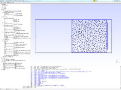
| + | [[File:TRCLUTTER_onelab.png|250px|frameless|alt=Geometry and ONELAB interface for heterogeneous medium|Geometry and ONELAB interface for heterogeneous medium.]] | ||
| + | [[File:TRCLUTTER_monoRE.png|250px|frameless|alt=Real part of the back propagated field|Real part of the back propagated field in a heterogeneous medium (monochromatic wave).]] | ||
| + | [[File:TRCLUTTER_mono.png|250px|frameless|alt=Absolute value of the back propagated field|Absolute value of the back propagated field in a heterogeneous medium (monochromatic wave).]] | ||
| + | |||
| + | And second, for a polychromatic wave (same parameters as for the homogeneous medium). The focal spot is clearly sharper for the heterogeneous medium (on the left the real part of the back propagated field, and on the right, its absolute value): | ||
| + | |||
| + | [[File:TRCLUTTER_bandwidthRE.png|250px|frameless|alt=Real part of the back propagated field in a heterogeneous medium (polychromatic wave)|Real part of the back propagated field in a heterogeneous medium (polychromatic wave).]] | ||
| + | [[File:TRCLUTTER_bandwidth.png|250px|frameless|alt=Real part of the back propagated field in a heterogeneous medium (polychromatic wave)|Real part of the back propagated field in a heterogeneous medium (polychromatic wave).]] | ||
== References == | == References == | ||
Latest revision as of 19:30, 14 December 2015
|
2D model of time reversal of acoustic waves.
|
|
|---|
|
Download model archive (time_reversal.zip) |
Contents
Additional information
To run the time reversal model, open TR.pro with Gmsh.
The experiment and the code
The model presented here was used in the PhD of B. Thierry [1] (who also wrote the code) to study the super resolution phenomenon in a deterministic medium and in the time harmonic regime.
Time reversal mirrors
The principle of time reversal is to use the reversibility of the wave equation in non dissipative media to back-propagate a signal on the source that first emitted it[2]. Time Reversal Mirrors (TRM), designed by Matthias Fink and his team in the 90's, are composed of a large number of transducers which can play alternatively the role of emitters and receivers. Associated to a numerical treatment module, they are able to record a signal, time reverse it, and back propagate it into the medium. The applications are numerous, such as submarine communication or kidney stone destruction.
Super resolution phenomenon
In a homogeneous medium, the wave back-propagated by the TRM focuses the source with a resolution generally given by $$ R = \frac{\lambda d}{a}, $$ where
- $\lambda = 2\pi/k$ is the central wavelength
- $d$ is the distance between the TRM and the source
- $a$ is the aperture of the TRM (its size for a linear mirror)
When the medium is heterogeneous, it is well-known that the back propagated wave will still focus on the point source with moreover a more accurate precision than in the homogeneous medium. In the litterature, this is generally imputed to the multi-pathing effect: the multiple scattering produces multiple paths between the sources and the mirror, which then receives more information compared to the same experiment in a homogeneous medium.
Time reversal experiment
Consider a point source $\mathbf{s}$ and a rectangular time reversal mirror $\mathcal{M}$ placed at finite distance of the source. The experiment can be split into three steps
- First, the source emits a wave that propagates throughout the medium
- Second, the TRM receives and records the wave
- Finally, it back-propagates it into the medium. The back-propagated field should then focus on the point source.
The context of the experiment is the following:
- The time reversal mirror is non intrusive (does not reflect waves), continuous and thick. This last condition is to avoid cracks in the mesh.
- Waves are assumed to be time harmonic of pulsation $\omega$: $\mathscr{U}(\mathbf{x}, t) = u(\mathbf{x})e^{-ikct}$, where $k= \omega/c$ and $c$ is the speed of sound in the vacuum.
- The time-harmonic assumption implies that the time reversal operation is nothing but a phase conjugation.
Context of the code
The simulations presented here are achieved in the time-harmonic regime and in two dimensions. The equation to be solved is then the Helmholtz equation. The heterogeneous medium is modelled as multiple circular obstacles with an inner wavelength (a contrast). The wavenumber, even if not fully random, is still randomized by the position of the disks and the constrast function. The code allows to:
- Simulate the time reversal experiment in a homogeneous medium (no obstacles)
- Study the super resolution phenomenon by adding circular scaterrers between the source and the TRM
- For both media, monochromatic waves are available (one frequency) or point source waves with a bandwidth, which permits to simulate time-dependent problems (but is highly time consuming, in terms of CPU usage).
In addition, the graphical interface allows to:
- Place the TRM and the point source
- Specify the aperture of the mirror
- Add the obstacles, randomly placed in a customizable box.
- The contrast function can be ramdonized or be manually specified, either the same for each obstacle or not.
Mathematical problem (monochromatic wave)
Modelling
Let $M$ random disks $\Omega^-_p$ be placed between the source and the mirror, with $M$ possibly equal to $0$ (homogeneous medium). Let the three step, emission, reception/time reversal and back propagation, be mathematically modelled as follows:
- Emission: let $u_E$ be the wave emitted by the point source $\mathbf{s}$. Thus, $u_E$ is the solution of
\begin{equation}\label{eq:ue} \begin{cases} (\Delta + k^2n^2) u_E = -\delta_{\mathbf{s}} & \text{ in } \mathbb{R}^2,\\ u_E \text{ outgoing}. \end{cases} \end{equation} Operator $\Delta v := \sum_{j=1}^2 \partial^2_{x_j}v$ is the Laplacian operator, $\delta_{\mathbf{s}}$ is the Dirac distribution centered on $\mathbf{s}$ and the first equation is known as the Helmholtz equation. The quantity $k$ is the wavenumber and $n$ is the contrast function such that $$ n(\mathbf{x})=\begin{cases} {\rm n}_p & \text{ if }\mathbf{x}\in\Omega^-_p,\\ 1 & \text{ otherwise.} \end{cases} $$ The outgoing condition stands for the Sommerfeld radiation condition at infinity $$ \lim_{\|\mathbf{x}\|\to\infty} \frac{1}{\|\mathbf{x}\|^{1/2}}\left(\nabla u \cdot \frac{\mathbf{x}}{\|\mathbf{x}\|} - iku\right) = 0. $$ The unique solution of problem \ref{eq:ue} is nothing but the Green function $G_k^n(\cdot, \mathbf{s})$ centered on $\mathbf{s}$. $$ \forall \mathbf{x}\neq\mathbf{s},\qquad u_E(\mathbf{x})= G_k^n(\mathbf{x},\mathbf{s}). $$ In the homogeneous case ($n=1$), an analytic expression of the emitted wave $u_E^0$ is known since the Green function, denoted by $G_k^0(\cdot, \mathbf{s})$, is given by: $$ \forall \mathbf{x}\neq\mathbf{s},\qquad G_k^0(\mathbf{x},\mathbf{s}) = \frac{i}{4}H^{(1)}_0(k\|\mathbf{x}-\mathbf{s}\|), $$ where $H^{(1)}_0$ is the zeroth order Hankel function of the first kind. In a heterogeneous medium and except for particular case, the Green function is unknown and must be approximated numerically.
- Reception: the TRM $\mathcal{M}$ measures the emitted field ($u_E|_{\mathcal{M}}$) and time-reversed it. As highlighted above, this operation is equivalent to a phase conjugation: $\overline{u_E}|\mathcal{M}$.
- Finally, the mirror back-propagates the signal. This last step is modelled as new wave $u_{back}$, solution of the following problem
\begin{equation}\label{eq:uback} \begin{cases} (\Delta + k^2) u_{back} = -\overline{u_E}|_{\mathcal{M}} = -\overline{G_k^n(\cdot,\mathbf{s})}|_{\mathcal{M}} & \text{ in } \mathbb{R}^2,\\ u_{back} \text{ outgoing}. \end{cases} \end{equation} The expression of $u_{back}$ is hence given by $$ \forall \mathbf{y}\in \mathbb{R}^2\setminus\overline{\mathcal{M}}, \qquad u_{back}(\mathbf{y}) = \int_{\mathcal{M}} G_k^0(\mathbf{x},\mathbf{y}) \overline{u_E(\mathbf{x})}\; {\rm d}\mathbf{x}. $$ Replacing $u_E$ by the Green function leads to a convolution product between Green functions: $$ \forall \mathbf{y}\in \mathbb{R}^2\setminus\overline{\mathcal{M}}, \qquad u_{back}(\mathbf{y}) = \int_{\mathcal{M}} G_k^n(\mathbf{x},\mathbf{y}) \overline{G_k^n(\mathbf{x},\mathbf{s})}\; {\rm d}\mathbf{x}. $$ For a homogeneous medium, as the Green function is known explicitely, so is the back propagated wave. This function can be plot directly with, e.g. a Python script, Matlab, Scilab, etc. With GMSH/GetDP, $u_{back}$ will however be computed by solving problem \ref{eq:uback}, but using the value of the Green function. For the heterogenous case and as the Green function is unknown, the emission and the back propagation steps are both computed numerically.
Theoretical results (homogenous medium only)
Propositions 3.8 and A.7 (appendix) of [1], shows the focusing property of the back propagated field for a thin and a thick TRM in 2 dimensions. As only a thick TRM is considered here, then only this result is summaries in this page. First, let be introduced the cone $\mathcal{C}$ of apex $\mathbf{s}$ and basis the mirror (see figure on right). Then, when the wavenumber $k$ tends to infinity, the back-propagate field $u_{back}$ focuses on the point source $\mathbf{s}$ in the sens that
- if $\mathbf{y} \in \mathbb{R}^2\setminus\overline{\mathcal{C}}$, then $|u_{back}(\mathbf{y})| = O(k^{-2})$,
- if $\mathbf{y} \in \mathcal{C}$, then $ |u_{back}(\mathbf{y})| = O(k^{-3/2})$,
- if $\mathbf{y} = \mathbf{s}$, then $ |u_{back}(\mathbf{y})| = O(k^{-1})$.
Mathematical problem (Band of frequencies)
This example is also the opportunity to show results using a band of frequencies. In that case, $k\in[k_0 - \Delta_k, k_0+\Delta_k]$, with, e.g. $k_0 =10$ and $\Delta_k = k_0/5$.
Emitted wave
The emitted wave $\mathscr{U}_E$ is then obtained by integrating over all the frequencies: $$ \mathscr{U}_E(\mathbf{x}, t) = \int_{k=k_0-\Delta_k}^{k_0+\Delta_k} u_E^k(\mathbf{x})e^{-i k ct}\;{\rm d}k = \int_{k=k_0-\Delta_k}^{k_0+\Delta_k} G_k^n(\mathbf{x})e^{-i k ct}\;{\rm d}k, $$ where $c$ is the velocity in the medium.
Back propagated wave $\mathscr{U}_{back}$ by the TRM
Recall that the expression of the back propagated field $u_{back}(\cdot\,,k)$ of frequency $k$, in the time harmonic regime, is given by, $$ \forall k\in[k_0 - \Delta_{k},k_0 + \Delta_{k}],\forall\mathbf{y}\in\mathbb{R}^{3}\setminus\overline{\mathcal{M}},\qquad u_{back}(\mathbf{y},k) = \int_{\mathcal{M}}\overline{G_{k}^n(\mathbf{x},\mathbf{s})}G_{k}^n(\mathbf{x},\mathbf{y})\;{ \rm d}\mathbf{x}. $$ The back propaged wave $\mathscr{U}_{back}$ is hence given by $$ \forall\mathbf{y}\in\mathbb{R}^{3}\setminus\overline{\mathcal{M}},\qquad \mathscr{U}_{back}(\mathbf{y},t) = \int_{k=k_0-\Delta_k}^{k_0+\Delta_k}\int_{\mathcal{M}}\overline{G_{k}^n(\mathbf{x},\mathbf{s})}G_{k}^n(\mathbf{x},\mathbf{y})\;{ \rm d}\mathbf{x} e^{-ikct}{\rm d}k. $$
$3$D and homogeneous medium: theoretical results
In the $3$D and homogeneous case, the expression of the emitted field reduces to $$ \forall t \in\mathbb{R}, \forall\mathbf{x}\in\mathbb{R}^{3}\setminus\{\mathbf{s}\}, \qquad \mathscr{U}_E(\mathbf{x},t) = \frac{\Delta_k{\rm sinc}\left[\Delta_k\left(\|\mathbf{x}-\mathbf{s}\|-ct\right)\right] e^{ik_0\left(\|\mathbf{x}-\mathbf{s}\| - ct\right)}}{2\pi\|\mathbf{x}-\mathbf{s}\|}, $$ where ${\rm sinc}(x) = \sin(x)/x$. Remark first that, due to the quantity $e^{ik_0\left(\|\mathbf{x}-\mathbf{s}\| - ct\right)}$, the wave $\mathscr{U}_E$ is propagating in a radial direction with respect to $\mathbf{s}$. The modulus of $\mathscr{U}_E(\mathbf{x},t)$ especially depends on the cardinal sine term, as: $$ \forall t \in\mathbb{R}, \forall\mathbf{x}\in\mathbb{R}^{3}\setminus\{\mathbf{s}\}, \qquad \left|\mathscr{U}_E(\mathbf{x},t)\right| = \left|\frac{\Delta_k{\rm sinc}\left[\Delta_k\left(\|\mathbf{x}-\mathbf{s}\|-ct\right)\right] }{2\pi\|\mathbf{x}-\mathbf{s}\|}\right|. $$ In particular, for a point $\mathbf{x}$ close to $\mathbf{s}$, the modulus of $\mathscr{U}_E(\mathbf{x},t)$ is reached at $t = 0$, when the value of the cardinal sine is $1$. This shows the presence of an impulsion at time $t=0$ at the source point. On the other hand, on a point $\mathbf{x}$ located at a distance $D$ from the source point, the modulus of $\mathscr{U}_E(\mathbf{x},t)$ is given by $$ \forall t \in\mathbb{R}, \qquad \left|\mathscr{U}_E(\mathbf{x},t)\right| = \left|\frac{\Delta_k{\rm sinc}\left[\Delta_k\left(D-ct\right)\right]}{2\pi D}\right|. $$ This quantity reaches its maximal value when $t = -D/c$. In other words, the perturbation created at time $t=0$ reaches the distance $D$ and thus the MRT, at time $t = D/c$.
On the other hand, the back-propagated field reduces to: \begin{equation}\label{eqRT:Ureyt} \mathscr{U}_{back}(\mathbf{y},t) = 2{\rm d}k\int_{\mathcal{M}} \frac{{\rm sinc}\left[{\rm d}k\left(\left[\|\mathbf{x}-\mathbf{y}\|-\|\mathbf{x}-\mathbf{s}\|\right] - ct\right)\right] e^{ik_0\left(\left[\|\mathbf{x}-\mathbf{y}\|-\|\mathbf{x}-\mathbf{s}\|\right]-ct\right)}}{\|\mathbf{x}-\mathbf{s}\|\|\mathbf{x}-\mathbf{y}\|} \;{\rm d}\mathbf{x}. \end{equation} It should be pointed out that on the point $\mathbf{y}=\mathbf{s}$, the cardinal sine term vanishes and the above expression reduces to $$ \mathscr{U}_{back}(\mathbf{s},t) = 2{\rm d}k \int_{\mathcal{M}} \frac{{\rm sinc}\left(-{\rm d}k ct\right)}{\|\mathbf{x}-\mathbf{s}\|^{2}} \; {\rm d}\mathbf{x} = 2{\rm d}k{\rm sinc}\left({\rm d}k ct\right) \int_{\mathcal{M}} \frac{{\rm d}\mathbf{x}}{\|\mathbf{x}-\mathbf{s}\|^{2}}. $$ Hence, when $\mathbf{y} = \mathbf{s}$, the modulus of $\mathscr{U}_{back}(\mathbf{s},t)$ reaches its maximal value at time $t = 0$. On the other hand and on a point $\mathbf{y}\in\mathbb{R}^{3}\setminus\overline{\mathcal{M}}$, when $t=0$ the equality \ref{eqRT:Ureyt} becomes $$ \forall\mathbf{y}\in\mathbb{R}^{3}\setminus\overline{\mathcal{M}},\qquad \mathscr{U}_{back}(\mathbf{y},t = 0) = 2{\rm d}k\int_{\mathcal{M}} \frac{{\rm sinc}\left[{\rm d}k\left(\|\mathbf{x}-\mathbf{y}\|-\|\mathbf{x}-\mathbf{s}\|\right)\right] e^{ik_0\left(\left[\|\mathbf{x}-\mathbf{y}\|-\|\mathbf{x}-\mathbf{s}\|\right]-ct\right)}}{\|\mathbf{x}-\mathbf{s}\|\|\mathbf{x}-\mathbf{y}\|} \;{\rm d}\mathbf{x}. $$ On $\mathbf{y} = \mathbf{s}$, the quantity $\mathscr{U}_{back}(\mathbf{y},t = 0)$ does not depend on $k$ anymore and reads as $$ \mathscr{U}_{back}(\mathbf{s},t = 0) = 2{\rm d}k\int_{\mathcal{M}} \frac{{\rm d}\mathbf{x}}{\|\mathbf{x}-\mathbf{s}\|^{2}}. $$ For every other point $\mathbf{y}$ (up to symetric points of $\mathbf{s}$ with respect to the TRM), the stationary phase theorem can be applied, as in the time harmonic regime. Hence, a decrease of $\left|\mathscr{U}_{back}(\mathbf{y},t = 0)\right|$ with respect to $k_0$ can be proven. This decrease is moreover stronger du to the presence of the cardinal sine term. As a consequence, at time $t = 0$, the wave $\mathscr{U}_{back}$ focuses on the point source $\mathbf{s}$.
Finally, remark that at $t=0$, the general expression of $\mathscr{U}_{back}$, becomes $$ \forall\mathbf{y}\in\mathbb{R}^{3}\setminus\overline{\mathcal{M}},\qquad \mathscr{U}_{back}(\mathbf{y},t = 0) = \int_{k_0-{\rm d}k}^{k_0+{\rm d}k} \mathscr{U}_{back}(\mathbf{y},k) \;{\rm d} k. $$ In other words, the wave $\mathscr{U}_{back}$ on $\mathbf{y}$ and at time $t=0$ is obtained by the sum of every time-harmonic fields $\mathscr{U}_{back}(\cdot\,,k)$, for $k\in[k_0-{\rm d}k,k_0+{\rm d}k]$. The quantity $\mathscr{U}_{back}(\mathbf{y},t = 0)$ can then be seen as an average over the frequencies $k$ of the different fields $u_{back}(\cdot\,,k)$.
Numerical resolution
Approximation with a PML
To be solved using finite element method, problem \ref{eq:uback} is truncated using a Perfectly Matched Layer (PML), as in the scattering problem with a PML.
Weak formulation
To simplify, the approximation of the back propagated field in $\Omega_e$ is still denoted by $u_{back}$ instead of $u^{PML}_{back}$. Function $u_{back}$ will be sough in the Sobolev space $H^1(\Omega_T)$and the weak formulation of problem \ref{eq:uback} reads as $$ \left\{ \begin{array}{l} \displaystyle{\text{Find } u \in H^1(\Omega_T) \text{ such that}}\\ \displaystyle{\forall u'\in H^1(\Omega_T),\qquad \int_{\Omega}D \nabla u \cdot\nabla u'\;{\rm d}\Omega - \int_{\Omega}k^2 S_{x_1} S_{x_2} uu'\;{\rm d}\Omega + \int_{\mathcal{M}} \overline{u_E} u'\;{\rm d}\mathcal{M} =0,} \end{array}\right. $$ where $u_E$ is here equal to the Green function: $u_E = G(\cdot,\mathbf{s})$.
Results
Homogeneous medium
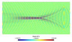
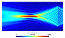
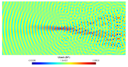
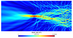
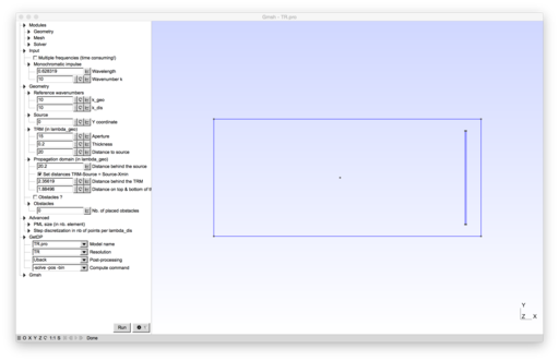
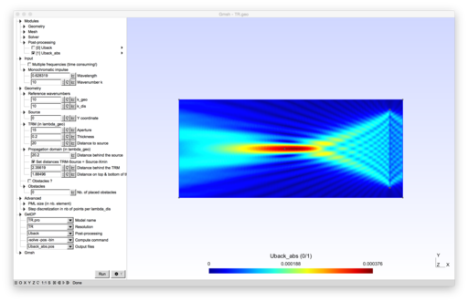
The three following pictures depict respectively the geometry, the real part of $u_{back}$ and the absolute value of $u_{back}$, with the following parameters ($\lambda_{geo} = 2\pi/k_{geo}$):
- $k_{geo} = 10$
- Distance between source and mirror: $20\lambda_{geo}$
- Aperture of the TRM: $15\lambda_{geo}$
- Thickness of the TRM: $0.2\lambda_{geo}$
- $k_{dis} = 15$
- $k = k_{geo} = 10$
For a monochromatic wave of frequency $k_0=k_{geo}$, which corresponds to a harmonic source, the results are:
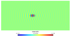
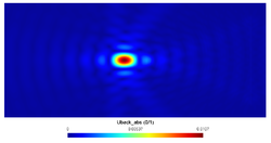
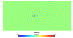
Now, using the same geometry, a polychromatic wave is used as emitted wave instead of a pulse. The frequency now lies between $[k_0-\Delta_k, k_0+\Delta_k]$ with $k_0 = k_{geo} = 10$ and $\Delta_k=k_0/5 = 2$. The segment $[8,12]$ is sampled by $64$ frequencies and here is the result (on left the real part of the back propagated field, and on the right, its absolute value):
Heterogeneous medium
The same geometry is used again but with arround 350 circular obstacles placed between the source and the mirror. They are all of radius $\lambda_{geo}/5$ and placed in a box between the source and the TRM. The results are the following, first for a monochromatic wave:
And second, for a polychromatic wave (same parameters as for the homogeneous medium). The focal spot is clearly sharper for the heterogeneous medium (on the left the real part of the back propagated field, and on the right, its absolute value):
References
- ↑ 1.0 1.1 B. Thierry, Analyse et Simulations Numériques du Retournement Temporel et de la Diffraction Multiple, PhD. Thesis, Université de Nancy, France, 2011, http://tel.archives-ouvertes.fr/tel-00651312/
- ↑ M. Fink and C. Prada. Acoustic time-reversal mirrors. Inverse Problems, 17(1) :1761–1773, 2001.
|
Model developed by B. Thierry.
|

