Magnetodynamics with cohomology conditions
|
Magneto-thermal model of an induction heating device.
|
 
|
|---|
|
Download model archive (indheat.zip) |
\(\renewcommand{\vec}[1]{\mathbf{#1}} \newcommand{\Grad}[1]{\mathbf{\text{grad}}\,{#1}} \newcommand{\Curl}[1]{\mathbf{\text{curl}}\,{#1}} \newcommand{\Div}[1]{\text{div}\,{#1}} \newcommand{\Real}[1]{\text{Re}({#1})} \newcommand{\Imag}[1]{\text{Im}({#1})} \newcommand{\pvec}[2]{{#1}\times{#2}} \newcommand{\psca}[2]{{#1}\cdot{#2}} \newcommand{\E}[1]{\,10^{#1}} \newcommand{\Ethree}{{\mathbb{E}^3}} \newcommand{\Etwo}{{\mathbb{E}^2}} \newcommand{\Units}[1]{[\mathrm{#1}]} \)
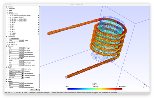
Here we represent an induction heating eddy current problem that utilizes the homology and cohomology solver of Gmsh. In this example application, alternating current fed into the inductor coil generates eddy currents in a workpiece inside the coil, causing the workpiece to heat up.
The electromagnetic modeling aspects of the problem turn out be subtle. So-called $A-V$ formulation of the problem is straightforward to implement, but it results a large linear system that might be difficult to solve. In the $T-\Omega$ formulation of the problem, same accuracy is achieved with a smaller linear system, but its implementation involves so-called thick-cuts, or source fields, that aren't discussed much in the finite element curriculum and may be difficult to produce. Here, we call them cohomology basis functions, and generate them using the cohomology solver implemented in Gmsh. The role the cohomology basis functions are first discussed in the $T-\Omega$ formulation and then for completeness, they are also expoited in the $A-V$ formulation to take an another perspective of their role in the electromagnetic modeling.
Contents
Problem definition
The domain
Let $M \subset \mathbb{R}^3$ and let $\partial M = S_1 \cup S_2$ so that $\partial S_1 = \partial S_2 = S_1 \cap S_2$ denote the 3D modeling domain and its 2D boundary that is decomposed in two parts. Furthermore, the domain $M$ is decomposed in a conducting subdomain $M_c$ and a non-conducting subdomain $M_a$ so that $M = M_c \cup M_a$ and $M_c \cap M_a = \partial M_c \cap \partial M_a$ hold. We assume that $M$ is connected and has no holes nor voids, i.e. its Betti numbers are $b_0(M)$ = 1 and $b_1(M) = b_2(M) = 0$.
The conducting subdomain $M_c$ consists of two parts: The workpiece being heated is a hollow cylinder around which the inductor coil wraps. The terminals of the inductor coil extend to the boundary $\partial M$ of the domain.
The boundary value problem
We solve time harmonic magnetoquasistatic approximation to the Maxwell's equations in $M$:
\begin{align} \Curl{\vec{h}} &= \vec{j}, & \Curl{\vec{e}} + i \omega \vec{b} &= 0 , \\ \Div{\vec{j}} &= 0 , & \Div{\vec{b}} &= 0, \\ \end{align} with constitutive equations \begin{align} \vec{b} &= \mu \vec{h} , & \vec{e} &= \rho \vec{j} . \end{align}
In order to treat the domain $M$ as a circuit element, we apply magnetic isolation at its boundary $\partial M$. This is achieved by the boundary condition \begin{align} \vec{b} \cdot \vec{n} = 0 \textrm{ on } \partial M. \end{align}
In the non-conducting domain $M_a$ we have no currents: \begin{align} \Curl{\vec{h}} = 0 \textrm{ in } M_a, \end{align} and the current cannot pass from the conducting subdomain $M_c$ to the non-conducting subdomain $M_a$. Also, the current cannot pass through the boundary $\partial M$ to the non-conducting subdomain $M_a$. Thus, the conditions \begin{align} \vec{j} \cdot \vec{n} = 0 \textrm{ on } \partial M_a \cap \partial M_c \textrm{ and on } M_a \cap \partial M = S_2 \end{align} are required to hold at the interfaces. The terminals on $M_c \cap \partial M$ which connect the inductor coil to an external circuit are modeled as equipotential surfaces, i.e. as perfectly conducting surfaces. Thus, we apply a boundary condition \begin{align} \vec{e} \times \vec{n} = 0 \textrm{ on } M_c \cap \partial M = S_1 \end{align} on them.
Note that the boundary $\partial M$ is now decomposed on two parts according to the boundary condition applied on it: $\partial M = S_1 \cap S_2$. On $S_1 = M_c \cap \partial M$ we have the condition $\vec{e} \times \vec{n} = 0$ and on $S_2 = M_a \cap \partial M$ we have the condition $\vec{j} \cdot \vec{n} = 0$. We can either drive the problem by the net current $I_s$ through the terminals, or by the net voltage difference $V_s$ between the terminals: \begin{align} \int_{\zeta} \vec{e} \cdot \mathrm{d} \vec{l} &= V_s, \\ \int_{\Sigma} \vec{j} \cdot \vec{n} \, \mathrm{d} a = \int_{\Sigma} \Curl{\vec{h}} \cdot \vec{n} \, \mathrm{d} a = \int_{\partial \Sigma} \vec{h} \cdot \mathrm{d} \vec{l} &= I_s, \\ \end{align} where $\zeta$ is a curve on $S_2$ between the terminals on $S_1$ and $\Sigma \subset M$ is a surface that isolates the terminals. The boundary $\partial \Sigma$ also lies on the part $S_2$ of the boundary of the domain. In addition, the fields $\vec{e}$ and $\vec{j}$ are linked by the constitutive equation $\vec{e} = \rho \vec{j}$. All these considerations hint a duality between the electric field $\vec{e}$ and the current density $\vec{j}$ and between the voltage and the current conditions.
A class $[\zeta]$ of curves on $S_2$ between the terminals on $S_1$ belong to so-called relative homology space $H_1(S_2, \partial S_2)$, while the class $[\partial \Sigma]$ of curves belong to a homology space $H_1(S_2)$. The integral conditions on fields $\vec{e}$ and $\vec{j}$ (or $\vec{h}$) fixing $V_s$ and $I_s$ are called cohomology conditions, since they consider integrals over an element of a homology space.
$T-\Omega$ potential formulation
In this formulation we solve for the magnetic field $\vec{h}$ in $M$ to obtain the current density $\vec{j} = \Curl{\vec{h}}$ in $M_c$. Let us denote by $N(M_a)$ the set of nodes in the mesh of $M_a$ and by $E(M_c \setminus (\partial M_a \cap \partial M_c))$ the set of edges in $M_c$ that are not on the interface $\partial M_a \cap \partial M_c$ of conducting and non-conducting subdomains.
Denote by $\mathsf{n}_i$ nodal shape functions associated with the nodes of the mesh and by $\mathsf{e}_i$ edge elements associated with the edges of the mesh. By $\mathsf{E}_i$ we denote so-called 1-cohomology basis function, which is an integer combination of edge elements on $M$: $$ \mathsf{E}_i = \sum_j z^j_i \mathsf{e}_j $$ where the integer coefficient vector $\vec{z}_i$ is produced by the cohomology solver of Gmsh.
Now, the unknown magnetic field $\vec{h}$ is of the form $$ \vec{h} = \sum_{i \in N(M_a)} \phi_i \Grad{\mathsf{n}_i} + \sum_{i \in E(M_c \setminus (\partial M_a \cap \partial M_c))} t_i \mathsf{e}_i + I_1 \mathsf{E}_1 + I_2 \mathsf{E}_2, $$ where the cohomology basis functions $\mathsf{E}_1$ and $\mathsf{E}_2$ are produced by the computation of the cohomology space $H^1(M_a)$ in Gmsh. That is, the function space from which we look for the approximate solution of $\vec{h}$ is spanned by nodal shape functions $\mathsf{n}_i$ of $M_a$, edge elements $\mathsf{e}_i$ of $M_c \setminus (\partial M_a \cap \partial M_c)$, and by the cohomology basis functions $\mathsf{E}_i$ of the cohomology space $H^1(M_a)$. Those functions shall also serve as the test functions in the following weak formulation.
The weak formulation is \begin{align} -\int_M \mu \vec{h} \cdot \vec{h}' \, \mathrm{d} V &= 0 \quad \forall \, \vec{h}' \\ \int_{M_c} \rho \Curl{\vec{h}} \cdot \Curl{\vec{h}} \, \mathrm{d} V + i \omega \int_M \mu \vec{h} \cdot \vec{h}' \, \mathrm{d} V &= - \int_{S_2} \vec{e} \times \vec{h}' \cdot \vec{n} \, \mathrm{d} a \quad \forall \, \vec{h}', \end{align} where \begin{align} \vec{h}' \in \{ \Grad{\mathsf{n}_i}, \mathsf{e}_i, \mathsf{E}_1, \mathsf{E}_2\} & \textrm{ and } & \int_{S_2} \vec{e} \times \vec{h}' \cdot \vec{n} \, \mathrm{d} a = \begin{cases} V_i & \textrm{ when } \vec{h}' = \mathsf{E}_i \\ 0 & \textrm{ otherwise. } \end{cases} \end{align} By plugging in the expression for $\vec{h}$ one can construct a linear system from which the unknown coefficients $\phi_i$, $t_i$ and $V_i$ or $I_i$ can be solved. Note that either $V_i$ or $I_i$ from both pairs $(V_1, I_1)$ and $(V_2, I_2)$ must be fixed in order to get a unique solution.
$A-V$ potential formulation
In this formulation we solve for the vector potential $\vec{a}$ of the magnetic flux density $\vec{b}$ in $M$ and for the curl-free part $\boldsymbol{\epsilon}$ of the electric field $\vec{e}$ in $M_c$ to obtain the current density $\vec{j} = \rho^{-1} \vec{e} = \rho^{-1} (i \omega \vec{a} + \boldsymbol{\epsilon})$ in $M_c$.
The unknown magnetic vector potential $\vec{a}$ is of the form $$ \vec{a} = \sum_{i \in E(M \setminus \partial M)} a_i \mathsf{e}_i. $$ That is, the function space from which we look for the approximate solution of $\vec{a}$ is spanned by edge elements $\mathsf{e}_i$ of $M \setminus \partial M$. Those functions shall also serve as the test functions in the following weak formulation.
The unknown curl-free part $\boldsymbol{\epsilon}$ of the electric field is of the form $$ \boldsymbol{\epsilon} = \sum_{i \in N(M_c \setminus S_1)} \varphi_i \Grad{\mathsf{n}_i} + V_1 \mathsf{E}_1 + V_2 \mathsf{E}_2, $$ Where the cohomology basis functions $\mathsf{E}_1$ and $\mathsf{E}_2$ are produced by the computation of the relative cohomology space $H^1(M_c, S_1)$ in Gmsh. That is, the function space from which we look for the approximate solution of $\boldsymbol{\epsilon}$ is spanned by nodal shape functions $\mathsf{n}_i$ of $M_c \setminus S_1$, and by the cohomology basis functions $\mathsf{E}_i$ of the cohomology space $H^1(M_c, S_1)$. Those functions shall also serve as the test functions in the following weak formulation.
The weak formulation is \begin{align} \int_M \mu^{-1} \Curl{\vec{a}} \cdot \Curl{\vec{a}}' \, \mathrm{d} V + \int_{M_c} \rho^{-1} \boldsymbol{\epsilon} \cdot \vec{a}' \, \mathrm{d} V + i \omega \int_{M_c} \rho^{-1} \vec{a} \cdot \vec{a}' \, \mathrm{d} V &= 0 \quad \forall \, \vec{a}' \\ \int_{M_c} \rho^{-1} \boldsymbol{\epsilon} \cdot \boldsymbol{\epsilon}' \, \mathrm{d} V + i \omega \int_{M_c} \rho^{-1} \vec{a} \cdot \boldsymbol{\epsilon}' \, \mathrm{d} V &= - \int_{S_1} \vec{j} \varphi' \, \mathrm{d} a \quad \forall \, \boldsymbol{\epsilon}' \end{align} where \begin{align} \vec{a}' \in \{\mathsf{e}_i\}, \quad \boldsymbol{\epsilon}' \in \{ \Grad{\mathsf{n}_i}, \mathsf{E}_1, \mathsf{E}_2\}, & \textrm{ and } & \int_{S_1} \vec{j} \varphi' \, \mathrm{d} a = \begin{cases} I_i & \textrm{ when } \boldsymbol{\epsilon}' = \mathsf{E}_i \\ 0 & \textrm{ otherwise. } \end{cases} \end{align} By plugging in the expressions for $\vec{a}$ and $\boldsymbol{\epsilon}$ one can construct a linear system from which the unknown coefficients $a_i$, $\varphi_i$, and $V_i$ or $I_i$ can be solved. Note that either $V_i$ or $I_i$ from both pairs $(V_1, I_1)$ and $(V_2, I_2)$ must be fixed in order to get a unique solution.
Cohomology conditions
In both formulations, if the cohomology basis function $\mathsf{E}_1$ corresponds to the net current $I_s$ or the net voltage $V_s$ in the inductor coil, $I_1 = I_s$ and $V_1 = V_s$ hold. If cohomology basis function $\mathsf{E}_2$ corresponds to the net current or voltage in the workpiece, one should set $V_2 = 0$. That is, one drives the problem by setting either the source current $I_s$ or the source voltage $V_s$, and the other quantity together with the net current $I_2$ in the workpiece are solved as part of the finite element solution.
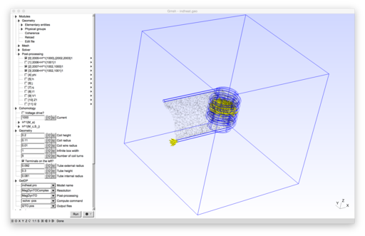
The implementation below produces such cohomology basis functions $\mathsf{E}_1$ and $\mathsf{E}_2$ as described above.
|
Model developed by M. Pellikka, S. Suuriniemi, L. Kettunen and C. Geuzaine.
|